


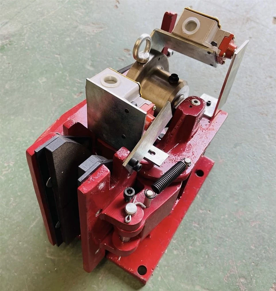

Hydraulic Fail-Safe Brakes are spring-applied, hydraulic-release braking systems engineered to provide automatic braking when hydraulic pressure is lost.
Operation Mode: Normally Closed (Spring-applied for instant braking upon hydraulic pressure loss).
Disc Thickness Compatibility: 15 mm or 30 mm optimized profiles.
Clamping Force Range: 1,650 N up to 288,000 N (Custom heavy-duty configurations available).
How Hydraulic Fail-Safe Brakes Work
• Hydraulic pressure retracts the piston rod, opening the brake arms.
• The brake disc rotates freely during normal operation.
• Hydraulic pressure is lost, or the system shuts down.
• Disc springs push the brake arms, pressing brake pads onto the disc.
• The equipment safely decelerates and stops.
Features
Fast Response
0.15–0.2s response time for immediate braking during power or hydraulic failure.
Intelligent Monitoring
Integrated PLC sensors provide real-time brake status and pad wear monitoring.
Long Service Life
Wear-resistant organic/sintered pads deliver a stable friction coefficient and reduced maintenance requirements.
Automatic Fail-Safe Protection
Spring-applied design automatically engages the brake when hydraulic pressure is lost.
Hydraulic fail-safe brake

Technical data
| 5SH | 450SH | 4SH | 3SH | |
| Maximum braking force (N) | 1650 | 3340 | 5880 | 10170 |
| Release pressure (bar) | 100 | 100 | 100 | 100 |
| Response time (s) | 0.15 | 0.15 | 0.2 | 0.2 |
| Weight (kg) | 27 | 28 | 62 | 95 |
| Disk diameter Φ B (mm) | 315 | 355 | 400 | 450 | 500 | 560 | 630 | 710 | 800 | |
| 5SH | Maximum braking torque (N.m) | 190 | 220 | 260 | 300 | 340 | 390 | 460 | ||
| A(mm) | 159 | 165 | 172 | 179 | 187 | 195 | 206 | |||
| C(mm) | 99 | 119 | 142 | 167 | 192 | 223 | 258 | |||
| 450SH | Maximum braking torque (N.m) | 380 | 450 | 510 | 600 | 680 | 770 | 900 | 1030 | 1180 |
| A(mm) | 159 | 165 | 172 | 179 | 187 | 195 | 206 | 218 | 231 | |
| C(mm) | 99 | 119 | 142 | 167 | 192 | 223 | 258 | 298 | 344 | |
| 4SH | Maximum braking torque (N.m) | 950 | 1120 | 1270 | 1500 | 1750 | 2000 | |||
| A(mm) | 225 | 232 | 241 | 251 | 262 | 274 | ||||
| C(mm) | 133 | 157 | 185 | 218 | 256 | 299 | ||||
| 3SH | Maximum braking torque (N.m) | 1600 | 1820 | 2100 | 2500 | 2900 | 3350 | |||
| A(mm) | 287 | 295 | 305 | 317 | 331 | 346 | ||||
| C(mm) | 103 | 127 | 155 | 188 | 226 | 269 | ||||
Overall Dimensions Table
| Model | E | F | G | H | K | M | N | S | T | R | d | m | n | α° |
| 5SH | 200 | 245 | 155 | 15 | 280 | 15 | 87.5 | 175 | 120 | 200 | 15 | 42 | 90 | 13° |
| 450SH | 200 | 245 | 155 | 15 | 280 | 15 | 87.5 | 175 | 120 | 200 | 15 | 42 | 90 | 13° |
| 4SH | 260 | 355 | 85 | 20 | 343 | 20 | 117.5 | 210 | 165 | 270 | 22 | 57 | 122 | 17° |
| 3SH | 360 | 490 | 80 | 25 | 435 | 20 | 117.5 | 210 | 165 | 270 | 22 | 68 | 128 | 20° |
ST1SH/ST2SH/ST3SH Hydraulic Fail-Safe Brake
Spring-applied, hydraulically released – suitable for disc thickness: 30 mm

Technical data
| ST1SH | ST2SH | ST3SH | ||||
| Maximum braking force (N) | Emergency braking | Service brake | Emergency braking | Service brake | Emergency braking | Service brake |
| 35000 | 25000 | 70000 | 50000 | 147000 | 105000 | |
| Release pressure (bar) | 100 | 100 | 100 | |||
| Response time (s) | 0.2 | 0.2 | 0.2 | |||
| Weight (kg) | 117 | 117 | 118 | |||
ST4SH Hydraulic Fail-Safe Brake
Spring-applied, hydraulically released – suitable for disc thickness: 30 mm

ST4SH series technical data
| Maximum braking force | ||
| Used for emergency braking | N | 120000 (pad A) ST4-A |
| Used for working braking | N | 90000 (pad M) ST4-M |
| Brake *Gap between pad and disc:1mm | ||
| Release pressure | bar | 100 |
| Fully released displacement capacity | cm³ | 110 Each piston 55cm³ |
| Total cylinder volume | cm³ | 408 Each piston 204cm³ |
| Response time A | s | 0.2 |
| Weight C | kg | 285 |
ST5SH Hydraulic Fail-Safe Brake
Spring-applied, hydraulically released
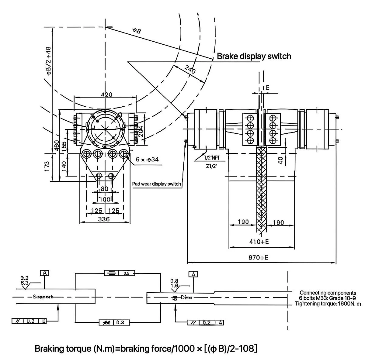
ST5SH series technical data
| Maximum braking force | ||
| Used for emergency braking | N | 293000 (pad A) ST5-A |
| Used for working braking | N | 220000 (pad M) ST5-M |
| Brake | ||
| Release pressure | bar | 190 |
| Fully released displacement capacity | cm³ | 120 Each piston 60cm³ |
| Total cylinder volume | cm³ | 678 Each piston 339cm³ |
| Response time | s | 0.2 |
| Weight | kg | 440 |
ST10SH/ST16SH/ST25SH/ST40SH Hydraulic Fail-Safe Brake
Spring-applied, hydraulically released

Technical data
| ST10SH | ST16SH | ST25SH | ST40SH | |
| Maximum braking force (N) | 81000 | 150000 | 200000 | 288000 |
| Gap (mm) | 2 | 1 | 1 | 2 |
| Release pressure (bar) | 130 | 150 | 150 | 190 |
| Response time (s) | 0.2 | 0.2 | 0.2 | 0.2 |
| Weight (kg) | 218 | 286 |
Overall Dimensions Table
| Model | S | T | H | d | M | N | G | L | F | K | Q | A | U | W | V | R |
| ST10SH | 45 | 45 | 190 | 25 | 95 | 130 | 55 | 300 | 315 | 190 | 45 | 35 | 88 | 48 | 288 | 648 |
| ST16SH | 65 | 70 | 260 | 32 | 110 | 135 | 65 | 345 | 370 | 205 | 45 | 35 | 88 | 48 | 288 | 600 |
| ST25SH | 72 | 90 | 302 | 32 | 130 | 150 | 65 | 380 | 400 | 220 | 60 | 50 | 88 | 48 | 288 | 650 |
| ST40SH | 100 | 100 | 367 | 41 | 168 | 219 | 100 | 522 | 462 | 268 | 119 | 100 | 90 | 50 | 306 | 630 |
Industry Solutions
Our hydraulic fail-safe brakes are engineered to deliver high-consequence stop and hold capabilities across harsh, high-duty environments globally:
Material Handling & Port Machinery: Container cranes (STS), gantry cranes, heavy-duty hoists, and winches.
Mining & Metallurgy: Conveyor belt drives, mine winders, hoists, and kiln drives.
Renewable Energy: Wind turbine yaw systems and main rotor emergency braking.
Oil & Gas / Marine: Drawworks, offshore winches, and marine propulsion shaft parking.
Quality Assurance and Trust Ecosystem
As an established industrial motion control manufacturer, our manufacturing process complies with strict quality protocols:
Testing & Validation: 100% load, response time, and pressure fatigue testing conducted before shipment.
Documentation Provided: Full material test certificates (MTR), dynamic testing logs, and comprehensive maintenance manuals with every delivery.
Compliance: Certified under ISO 9001:2015, with CE and ATEX explosion-proof compliant models available.


FAQ
Q: Are these brakes suitable for harsh marine or coastal outdoor environments?
A: Yes. Optional corrosion-resistant coatings and special protective treatments are available for harsh outdoor and marine environments.
Q: Do you provide CAD models for engineering integration?
A: Yes. STEP, IGES, and DWG drawings are available within 24 hours of sharing your technical requirements.
Q: What documentation is included in the shipment?
A: Every unit includes a Factory Test Certificate (Dynamic Load/Pressure logs), Material Test Reports (MTR), and an English Operation & Maintenance Manual.
Q: What is the typical lead time?
A: 2–3 weeks for standard models; 4–6 weeks for custom OEM batches. International shipping terms supported: FOB, CIF, DDP.
Hot Tags: hydraulic fail-safe brakes, China hydraulic fail-safe brakes manufacturers, suppliers, factory, Electric Hydraulic Arm Disc Brakes, Electric Hydraulic Disc Brakes, Electromagnetic Caliper Disc Brakes, Engineering Machinery Brakes, Hydraulic Caliper Disc Brakes, Hydraulic Fail Safe Brakes